Description
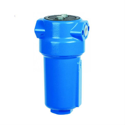
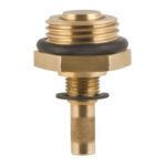
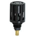
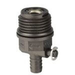
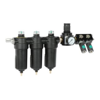
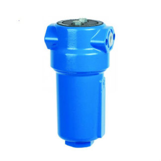
AAFFC filters are designed for protection of the downstream compressed air system and equipment with lower air flows against defects and other failures. They ensure high efficient removal of solid particles, water, oil aerosols, hydrocarbons, odour and vapours from compressed air systems up to 16 bar. Required compressed air quality according to standard ISO 8571-1 can be achieved with different grades of filter elements. Optional internal and external condensate drains should be used for efficient condensate draining from filter housing.
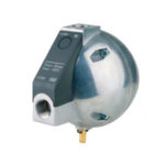
Condensate Drains:
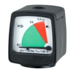
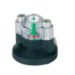
Differential Pressure Indicators:
 |
 |
 |
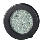 |
| Differential Pressure Gauge – MDAFC60 (20 bar) | Magnetic Differential Manometer – MDMFC40 (20 bar) | Differential Pressure Indicators – PDiFC16 (16 bar) | Humidity Indicator – CHIFC (20 bar) |
Accessories:
 |
 |
| Nipple – Operating Pressure: 20 bar | Sight Glass |
Characteristics
| Operating Pressure | 16 bar |
| Volume Flow Rate | 10 – 780 Nm³/h |
| Connections | 1/8″ to 11/2″ |
| Operating Temp. Range | 1,5 to 65 °C |
| Standard Colour | RAL 5012, RAL 7040 |
Applications
• general industrial applications
• automotive
• electronics
• food and beverage
• chemical
• petrochemical
• plastics
• paint
Technical Data, Dimensions & Mass
See PDF
Please note:
- Filter Elements A must be changed periodically to suit application, but at least every 6 months. Activated carbon filters must not operate in oil saturated conditions.
- Valid if S filter cartridge is installed upstream.
Correction Factors
| Operating Pressure [bar] | 2 | 3 | 4 | 5 | 6 | 7 | 8 | 9 | 10 | 11 | 12 | 13 | 14 | 15 | 16 |
| Operating pressure [psi] | 29 | 44 | 58 | 72 | 87 | 100 | 115 | 130 | 145 | 160 | 174 | 189 | 203 | 218 | 232 |
| Correction factor | 0.38 | 0.5 | 0.63 | 0.75 | 0.88 | 1 | 1.13 | 1.25 | 1.38 | 1.5 | 1.63 | 1.75 | 1.88 | 2 | 2.13 |

